Software Design Document
Purpose
This document details the current state of the design of the Aerie system. The document defines the components which make up the Aerie system and how these relate to the higher level system architecture. Additionally, design rationale and trade studies are described to provide guidance and support for design decisions. Where available, the many Aerie component interface definitions and relevant published software interface specifications will be provided inline or referenced.
Overview
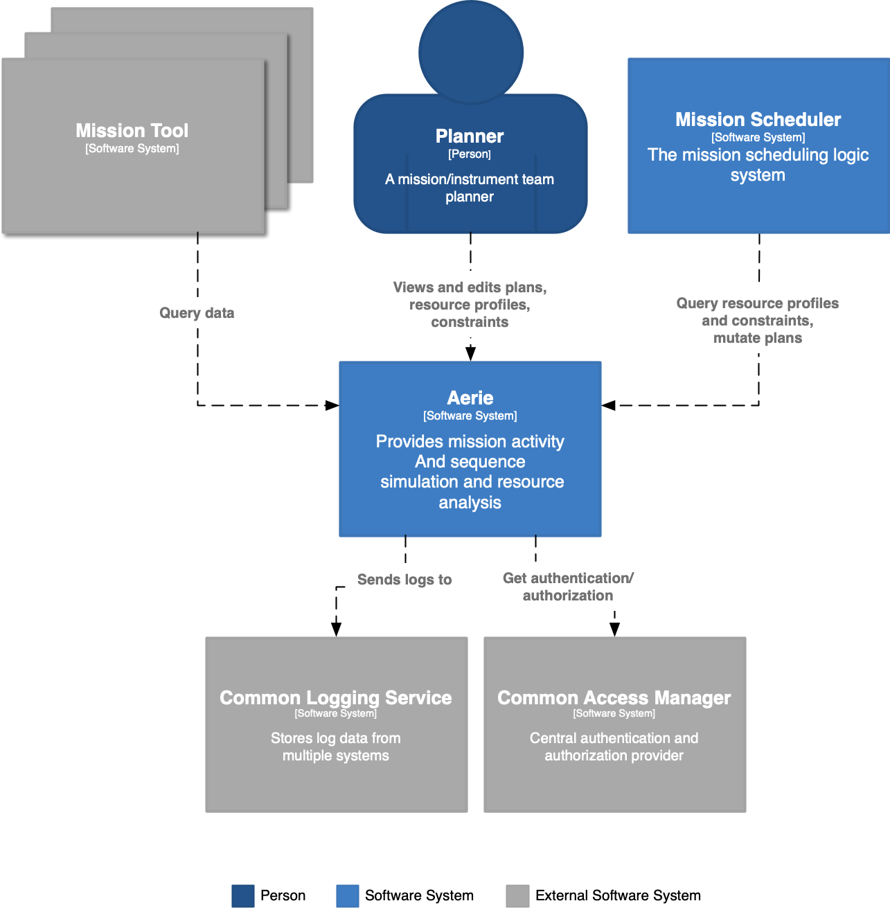
Aerie is an open-source extensible software system originally built for planning, scheduling, and commanding space missions. Initially developed by NASA's Advanced Multi-Mission Operations System (AMMOS), Aerie provides modeling and simulation capabilities that can be used for mission planning and analysis during project formulation all the way through operations, where it can be used to manage and validate spacecraft activity plans.
Aerie provides low-code solutions for authoring scheduling rules to autogenerate plans, authoring and evaluating constraints to assist with plan validation, and authoring logic to expand activities into sequences of commands for execution. Sequences can also be authored and edited independently following an open source sequencing specification, seq-json, that includes a variety of commanding styles (e.g. absolute, relative, command completion).
As a multi-tenant system, Aerie allows multiple distributed users to collaborate in real-time on a single plan or concurrently work on multiple plans for multiple missions. Additionally, Aerie's service-based architecture allows for efficient system deployment and scalability on the cloud.
References
If you are interested in learning how to use Aerie, a great place to start is our Fast Track. More detailed information on planning, scheduling, sequencing, and command expansion is available throughout our online documentation.
If you are interested in learning how to build and configure models to use with Aerie, please refer to our Mission Modeling documentation.
Aerie's design requirements are currently documented in the Aerie Software Requirements Document (SRD) delivered to AMMOS (DOC-002388 Rev. B). If you are interested in receiving a copy of this document, please contact aerie-support@googlegroups.com.
Detailed code documentation is also available in our Java Docs section.
Terminology and Notation
Container – in this document the term container primarily refers to the Container level of architecture as defined in the C4 Model approach to describing software architecture. Other types of container, such as a Docker container, will be denoted or made clear by context.
Mission model - The term "adaptation" has become significantly overloaded at JPL. The word is used in many different contexts to convey or denote a range of different and often unrelated entities or concepts. Often, the ability of one to understand the entity or concept which term denotes relies on one’s ability to understand the wider context in which it being used. This requires a burdensome amount of understanding of the domain before the term becomes specific and useful. Additionally, the boundary or extents of what the term denotes is unclear. Take for example the commonly termed mission planning adaptation. On first mention, it is not clear here if such usage indicates the specific APGen code written, or wider, the APGen code plus any modeling integrations, or wider still, the integrated system which performs a MP simulation. Finally, this term is very JPL centric and does not comport with other language in the domain of modeling, simulation, discrete event simulation etc.
As a result Aerie has chosen to use the term mission model to denote the modeling code (and integrations e.g. FMU) written, defined in a .JAR, which run as an Aerie simulation. It's specific as to the purpose of the code written, unambiguous (not confused with other terms in use), and better comports to the domain of simulation and modeling in general.
Parameter and Argument - in order to distinguish between the declared name and type of a function parameter, and a particular value that is provided to it, we use the word parameter to mean a name paired with a type, and we use the word argument to mean a value that is provided to a parameter.
Aerie System Design
System Architecture
This section describes the Aerie system architecture, the guiding component-based design philosophy, and an overview of the key components.
The architectural diagramming approach taken in this document follows the C4 Model for visualizing and discussing software architecture. This approach abstracts a software system into roughly four levels, Context, Containers, Components, and Code. A brief description of each level of abstraction is provided in Appendix A.
Aerie is designed to be incrementally evolvable - so that it can more easily be adapted to emergent user needs. The component based system design provides the benefits of system decomposition - giving the ability to expand the system without invasively changing the other components - and allowing the person working with the system to think about a small number of components at a time and not need to hold the whole system in their head at once. In the case where application need to accommodate growing or new capabilities, where those new capabilities are satisfied by separating a component into its own process, this can be done. A well designed monolith in many ways should resemble a distributed system. This means one should avoid shared state, strict definition and adherence to interfaces a service interface is equal to a component’s exposed interface. A message passing reactive system can exist whether the components are in the same process, in separate processes, or even separate infrastructure.
For example the merlin-worker is a part of the Merlin bounded context. Much of Aerie has been designed with the DDD principle of bounded contexts. Among the many implications of this is that the data within each bounded context shall only be manipulated by the components explicitly contained within the defined context. It is important not to mistake the fact that the merlin-worker is a separate container image as indicating that it is part of a separate bounded context. Rather, it is simply a separate container so that the merlin-server can account for the aforementioned process separation concerns. Therefore, each merlin-worker has a direct connection to the merlin database.
Container Level Component Overview
Merlin - Capabilities include plan management, managing the simulation and configuration of a mission model, managing simulation results, external dataset, and constraints management and checking.
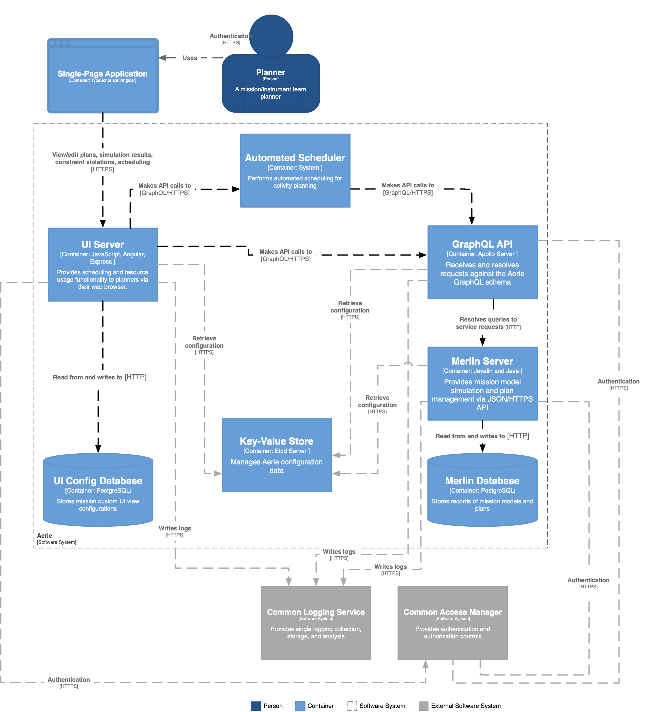
GraphQL API - The GraphQL gateway parses requests and resolves those requests with application internal components. The gateway is implemented via Hasura.
Aerie UI - The server provides a user interface which supports the myriad management and analysis processes performed during mission planning and mission operations. The server manages data regarding an individual user’s view layouts and selected user interface preferences.
Common Access Manager (CAM) - Aerie delegates authentication and authorization capabilities to an MGSS Common Access Manager server. Customers deploy their and configure a CAM to provide authentication and authorization of mission personnel.
Automated Scheduler - An automated scheduler operates external to the Aerie deployment and carries out computer aided mission activity scheduling by issuing queries and mutations against the Aerie GraphQL API. As a component external to the Aerie deployment, an automated scheduler can be developed by a customer in their preferred programming language and executed on infrastructure most suited to the computational needs of their scheduler’s algorithmic approach.
API
The Aerie GraphQL API presents a consistent application boundary to Aerie users. The API server enables the composition of multiple APIs (internal to the application) as a single API endpoint. The API component additionally provides a location in the system for the following needs:
- Manipulation of data
- Response Caching
Aerie API Needs
Evolve the internal APIs rapidly and the public APIs slowly.
The development of the Aerie user interface and application internal components proceeds in parallel. As a result, the user interface’s data needs imposes constraints on the definition of the system’s public API. The evolving nature of the user interface’s development makes it difficult to carry out an API design effort, as would be the case for a REST API architectural style. Further, the structure of resources needed by the highly configurable interface components within the user interface, makes defining an efficient set of resource endpoints prohibitively difficult. Such endpoints would require continuous editing and updating as development progressed.
Multiple clients and multiple different workflows for clients.
There exists a category of use cases in which customers develop custom Aerie client applications. Such customization requires the flexibility to easily define new data projections as simple queries constructed by a client. As a result, Aerie benefits from an API that supports high query flexibility from both the external client and internal services perspective.
Ability to dynamically reduce/transform response payloads.
Within the planning, scheduling and sequencing domain are a number of common list like data structures/concepts which are often quite large in size (number of elements). It is inefficient to impose upon any client seeking a particular view/aspect of the data structure to request and process the entire structure. For example, certain resources can’t be made "smaller" without compromising their intent. A Plan can be filtered but not sensibly partitioned. It is desirable that any client requesting such data structures be provided with an easily accessible means to query the data structure for the elements/projection of interest.
Custom queries and batch fetching.
The Aerie stores a number of significant mission data sources (E.g. activity plan, simulation results, and constraint violation results). Aerie must provide users flexible access to this data to support an arbitrary space of use cases for reporting, auditing and interfacing with third-party customers.
Trade Study
A trade study was conducted to evaluate available API products. A down selection of the tools left both the Tyk API gateway product and Apollo GraphQL Server product. The primary difference between these two products are their approach to exposing data. The Tyk gateway exposes system queries as Representational State Transfer (REST) endpoints while the Apollo GraphQL server exposes a single GraphQL query endpoint. The REST and GraphQL architectural styles present different approaches and embody contrasting capabilities. Representational State Transfer is an architectural style for distributed hypermedia systems. GraphQL is a query language for an API, exposed as a typed schema defined by a data graph. Table 3 presents a set of desirable API properties and the manifestation of each property for REST and GraphQL driven APIs.
Table 3 Comparison of REST and GraphQL capabilities
| System Property | REST | GraphQL |
|---|---|---|
| Modifiability | ✅ | Runtime inspection |
| Scalability | ✅ | ❌ |
| Portability | ✅ | ✅ |
| Reliability | ✅ | ✅ |
| Simplicity | ✅ | ✅ |
| Visibility | ✅ | ✅ |
| Performance | ✅ | ❌ |
| Discovery and Introspection | Limited | ✅ |
| Consistency | ❌ | ✅ |
| Ease of Server Development | ❌ | ✅ |
| Ease of Client Development | ❌ | ✅ |
| Over-fetching protection without proper API design | ❌ | ✅ |
| Active Community | ✅ | ✅ |
| Tooling Server | ✅ | ✅ |
| Tooling Client | ✅ | ✅ |
| Tooling API Management | Limited | ❌ |
| Maturity | ✅ | ❌ |
| Works with any data representation | ✅ | ❌ |
| Printed Books | ✅ | ✅ |
| Enterprise Ready | ✅ | ✅ |
The following is a discussion of the particular API qualities which provide for Aerie’s needs.
Discovery and Introspection - The GraphQL data graph schema provides a contract-like mechanism where requests and replies are inherently typed and can be directly validated and resolved based on those types. This contract like nature completely describes all possible requests/responses where a typed service provider won’t compile until it fully implements its contract. A typed service consumer will be type-checked at compile time, which helps to catch problems before deployment. Finally, it is unreasonable to expect that a well-performant API can be developed for every conceivable use case. As a result the improved introspection at the per field level in GraphQL allows for targeted optimization of common or slow queries.
Consistency - The API schema is typed and therefore either correct or not. As a result, there is an inherent consistency between client and server because both must abide by the generated schema.
Ease of Server Development - It is easier (development time, complexity) to develop and maintain data source resolvers as part of a GraphQL server. Well designed, true REST APIs take time and resources and are therefore more difficult to design and maintain. GraphQL relieves the project of that unnecessary burden.
Ease of Client Development - A client can develop against the exposed contract. A client can develop custom queries targeted to its own use cases to limit both over and under fetching. In many cases this may reduce latency and increase performance by limiting client side data manipulation/filtering.
Flexibility of API Design - User and mission needs are constantly evolving. GraphQL decouples the API allowing the Aerie team to make adjustments to the API according to evolving customer needs. Additionally, the increased granularity and visibility when auditing the frequency and combinations with which certain fields are queried, allows for clearly validated deprecation, removal, and changes of fields available in the API schema.
By adopting GraphQL we knowingly forgo certain capabilities/constraints of a REST API. Three cases have been identified as possible risks and sufficient mitigation options are identified:
Tooling API Management - GraphQL is a newer technological approach to APIs (2012).
Mitigation: Aerie has chosen to use Hasura, a major open source contributor to the GraphQL community.Caching - REST over HTTP benefits from existing HTTP server caching and browsers client caching mechanisms.
Mitigation: Most GraphQL libraries have caching mechanisms built in. Hasura caching must be handled with annotations/directives on the graph definition.Client-API Loose Coupling - Each new client application must make affordance at development time and hardcode custom queries and mutations as made possible by the Aerie GraphQL schema.
Mitigation: None. In the Aerie context this is not considered a benefit.
Hasura
Implementing an API requires developers to write a lot of repetitive code. Many API calls are simply Create, Read, Update, or Delete (CRUD) operations to the database. The translation of GraphQL queries to SQL can be automated to save developers a lot of toil. This is what Hasura does.
To add a new node to the GraphQL API graph, a developer needs to create the corresponding table in the database, and update the Hasura metadata, stored in yaml files, to communicate to Hasura that that table should be exposed via the API.
Hasura produces rich APIs that allow sorting and filtering data out of the box. This saves developers the work of adding sorting and filtering to each node individually.
As a result, Hasura boosts the productivity of the development team, and provides a higher quality API to users.
Merlin Server
The Merlin server supports the following capability areas:
- Mission model management
- Plan management
- Simulation execution and results management
- Constraints management and evaluation
There are two driving user stories which help define the core business logic of the Merlin server. The two user stories are:
- A user wants to create and edit an activity plan.
- A user wants to view the mission resource profiles of a simulated activity plan.
By providing for these two user stories the Merlin server is able to support many other more complex user stories.
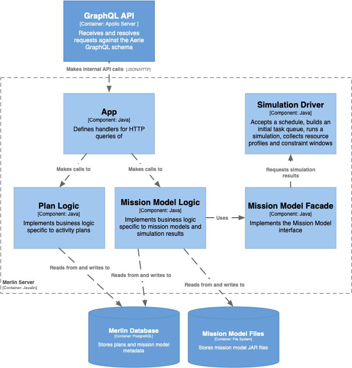
The Merlin server component diagram is show in Figure 3. There exist strong data coupling between the data contained in a Plan and the data defined in a mission model. To reduce the potential for significant data model duplication and intra container communication the server is designed as a single entity.
The Merlin server is implemented as a Javalin application. Javalin is a lightweight web framework implemented as a layer atop Jetty. The underlying Jetty server is fully configurable, providing SSL and HTTP2 capabilities. Javalin was chosen because it focuses only on providing a web application framework, it's simple to integrated, and demonstrates satisfactory performance (performance of raw Jetty code). Compared to the myriad other web application frameworks, Javalin is extremely simple in its implementation and use. The Aerie project has chosen not to use frameworks such as Spring, due to their steep learning curves, lack of focused capabilities, and burdensome dependencies and size.
The App component defines the configuration of the Javalin server and resolves calls to the Merlin server HTTP API to response handlers provided in the Plan Logic and Mission Model Logic components. The Plan Logic component encapsulates the business logic for managing and manipulating activity plans. The Mission Model Logic component manages mission models, simulation of those models, and the queries regarding results (resource profiles and constraints). The Mission Model Facade defines a set of queries that can be made of a mission model. These queries pertain to both, data defined by the mission model (activity types and resources), and data generated by simulating the mission model (resource profiles and constraint windows). The facade orchestrates the loading of a mission model, and makes transparent to the Mission Model Logic, the execution of a simulation by the Simulation Driver.
Components of merlin include:
- The Merlin App, which is responsible for providing an HTTP interface to Hasura
- The Simulation Driver, which is responsible for running a simulation
- The Simulation Engine, which is responsible for keeping track of what should happen next in a simulation
- Mission model logic, which is responsible for loading mission models from files, and interrogating them about their contents
- The Merlin Database is responsible for persisting and indexing planning and simulation data. The database includes stored procedures to provide certain functionality without needing to move data out of the database.
All of the components of Merlin read from and write to a single PostgreSQL database. The database maintains separate tables for each of the components. The Mission Model Logic stores the JAR files defining mission models in a file system.
Merlin Workers
The merlin worker component introduces a multi-tenancy capability for Aerie simulation. The driving use cases for the merlin worker architecture are:
- Executing multiple concurrent simulations
- Aerie is a multi-user application and needs to be able to execute multiple concurrent simulation requests.
- Separate process spaces to provide
- Protection against SPICE's non-thread safe implementation.
- The ability to reduce simulation time by executing simulations on computationally performant hardware, while running other Aerie components on more modest infrastructure.
Firstly, it is clear that threading concurrent simulation requests could have been a viable first step on the path if the SPICE library was thread safe. SPICE is not thread safe and therefore each library loaded in a process must be accessed by only one thread.
Secondly, simulation execution is the most computationally expensive process among the various Aerie components. While Aerie in general can be deployed to generally powerful compute resources, it is more cost efficient to deploy only the compute bounded portion of the process to dedicated compute resources. Separating out (decoupling) the merlin-worker's responsibilities into a separate process enables Aerie to be deployed across a number of hosts, where the merlin-worker containers are deployed to infrastructure tuned for simulation execution speed and the remainder of containers on modest hardware.
The worker subsumes the responsibility of running a simulation and writing the results to the merlin postgres database. The merlin-server processes a simulation request, creates the initial dataset tables and associations. The simulation_dataset entry is initially set with a status "pending". This status indicates that the simulation run is queued waiting for a worker to take the job. When a worker takes the job the status is updated (by the worker) to "incomplete".
The merlin-worker is a part of the Merlin bounded context. Much of Aerie has been designed with the DDD principle of bounded contexts. Among the many implications of this is that the data within each bounded context shall only be directly mutated by the components explicitly contained within the defined context. It is important not to mistake the fact that the merlin-worker is a separate container image as indicating that it is part of a separate bounded context. Rather, it is simply a separate container so that the merlin-server can account for the aforementioned process separation concerns. Therefore, each merlin-worker has a direct connection to the merlin database.
The postgres NOTIFY/LISTEN feature is used to NOTIFY workers LISTEN(ing) for newly created simulation jobs. The database trigger emits a notification with a payload containing the simulation revision data. Upon receiving a notification each worker will attempt to claim the simulation job by changing it's simulation_dataset status field to "incomplete". A simulation job is considered taken if this SQL operation is successful. Then the successful worker continues with executing the simulation. If the SQL operation is unsuccessful (e.g. another worker was successful in claiming a job earlier) then the worker handles the failure to claim the job and moves on to attempt claiming other jobs. One is assured that there will be no race conditions due to Postgres' ACID transaction processing.
Datastores
Aerie's datastores include both relational databases and the file system. A large majority of Aerie's data is considered to be structured data with a small amount of semi/un-structured data. The semi-structured is often in JSON form. A relational database is the appropriate choice when dealing with structured data. Aerie also uses the filesystem to store mission model .JAR files uploaded to Aerie.
Additional considerations include:
- Storing structured data directly and being able to retrieve and filter based on that structure fast at the database layer is important.
- Postgres has JSON and JSONB handling, making it possible to quickly filter on unstructured data as well. Other database systems, such as mariadb, store json as text and don't treat it specially.
- Design and selection criteria for the db
- Secure connections TLS
- Auth
- Redundancy/scalability
- Application components scalable on their own -> e.g. db scalable on their own
- Historically missions are insufficiently equipped in both the technical ability and resource (time/people/money) to manage large IT infrastructures. As such, it is advantageous for Aerie to minimize the number of database that may require maintenance (backup, updates, provisioning hardware) and to provide administrative infrastructure to carry out these tasks transparently.
- Backups and Migration
- What data is backed up
- Mission model JARs are not. It is expected that the code base which is compiled to the JAR is un configuration management and that a JAR can be reproduced at any time by the user.
- Plans, constraints, simulation resource profiles - all data in the PostgreSQL database should be backed up in case of system failure and migration between Aerie versions.
Deployment
Aerie deployment is designed to accommodate two user groups; the individual installation on a local machine and the installation on hosted infrastructure.
Each Aerie service is deployed as a Docker container with the deployment orchestrated by the Docker Compose utility. The Docker Compose utility creates up a single Docker network which enables dependent Docker containers to exchange messages with each other. Each Docker container joins the network and is both reachable by other containers on that network, and discoverable by them at a hostname identical to the container name. Aerie service containers have their IP and port numbers statically assigned within the Docker Compose YAML configuration file.
Authentication and Authorization
Aerie provides authentication and authorization capabilities via the Common Access Manager. Currently, authentication requests from the Aerie UI are proxied through the aerie-ui-server. It is prudent that Aerie not handle (proxy/store) any credential information, for any duration of time. As a result, Aerie authentication will soon be amended so requests for an authentication token are made directly to a CAM server instance with the Cross-Origin Resource Sharing (CORS) capability enabled.
Authorization is provided by configuring CAM policies. The Aerie GraphQL API Server manages authorization of API access and limits access based on user roles per API field granularity.
Data Model
Datasets
In Aerie, a dataset is a set of data describing several associated concepts. Each dataset can be broken down into three core pieces:
- Profiles
- Spans
- Events
Because a dataset conglomerates several types of data, the actual data within a dataset is spread across several database tables. Several of these tables that may contain many rows of data per dataset are partitioned by dataset ID, allowing for higher efficiency in working with those database tables. The partitions for a given dataset are created and deleted alongside the dataset itself automatically via postgres triggers.
Profiles
Profiles describe dynamic values whose behavior is defined in distinct
segments. Each profile has a type (real or discrete) governing the
dynamics it may exhibit in each segment, a name and an ID. This
information is stored in the profile table. The actual dynamics and
duration of each segment of a profile is stored in the
profile_segment table. Each segment's start is stored as an absolute
offset from the start of the dataset.
Spans
Spans describe windows of time via a start offset and duration. Each span must have an assigned type as well as a set of attributes, and may be specified as a child of another span by providing a parent ID.
Events
An event graph associated with a dataset may be stored using the
event and topic tables.
Simulation Datasets
One of the primary uses of datasets is to store simulation
results. Simulation results are stored by placing activity instances
in the span table, resource profiles in the profile and
profile_segment tables, and an event graph in the event and
topic tables. The simulation_dataset table is used to match a
simulation up with its associated dataset.
Each row of the simulation_dataset table defines all the information
about what was input to a simulation resulting in the associated
dataset. This includes the versions of the mission model, plan, and
simulation input that were used for the simulation run.
An insertion to simulation_dataset should only take the simulation
ID and offset from plan start from which the dataset should be
interpreted. When a simulation_dataset row is inserted, a trigger
runs to initialize the associated dataset row (filling in the
dataset_id field) and populate the revision columns with the current
revision of the associated mission_model, plan, simulation and
simulation_template. When one of these tables is updated, a separate
trigger will automatically mark all associated rows of
simulation_dataset as canceled by setting the canceled column to
true. Only the simulation_dataset representing the up-to-date
simulation results should not be canceled.
External Datasets
External datasets allow for users of our system to upload precomputed
profiles to be associated with a plan. The precomputed profiles are
stored in a dataset associated with a plan via the plan_dataset
table.
Similar to inserts on simulation_dataset, an insert to
plan_dataset should only take a plan ID and an offset from the
plan's start from which the dataset is to be interpreted. A trigger
will automatically insert a row to the dataset table, and populate
the dataset_id of the inserted row, to which precomputed profiles
can be added.
EDSLs
Aerie utilizes a number of EDSLs for parts of the system that require customization of behavior that is more complex than simple option changes and at a different cadence than mission models. We considered using custom DSL's, but the infrastructural work to build in all the capabilities we wanted (listed below in requirements) was prohibitive from a time-to-implement perspective, so we settled on doing EDSLs which use a pre-existing programming language and embeds a domain specific language component therein.
Currently these are Constraints, Scheduling Goals, and Command Expansion. The first of these to come about was Command Expansion, which laid the groundwork for a design that was easily extended to Constraints and Scheduling Goals. This section is written to tell the design/implementation story for all of these EDSLs.
Command Expansion Requirements
Command expansion is the process of taking activities in the plan and generating actual spacecraft commands from them. Much of the command expansion conceptual design was evolved from the ideas of the M2020 Scripted Expansion and SIE Sequence Generator systems and the MSL Master Submaster Generator before it.
Conceptually, command expansion is a simple functional map from activities in the map to they're implementing spacecraft commands. Activity → Commands
Due to the desire to abstract away the complexity of spacecraft commands to the simplicity of conceptual spacecraft activities, it is often more complex than a fixed set of commands or even a fixed set of commands with arguments that come from the activity parameters. As such, a more powerful method than simply templating out commands with substitution is desired.
On MSL, this was first captured in part by the Master Submaster Generator that had the entire plan in scope and composed the top level Master sequences and the second tier Submaster sequences. The architecture of that software, however, led it to become overly complex as it was using a visitor pattern over the plan to generate the sequences procedurally, which grew difficult to maintain over time. One of the biggest issues with this system is that documentation was sparse and there was no readily accessible way to check semantic correctness before execution, meaning the development cycle required repeatedly re-deploying and re-executing just to find out that a method being used did not exist or the data structure was different than expected.
On M2020, two systems were built with similar goals - the Scripted Expansion system took user defined python scripts that defined a single function expand that was passed a single activity and then the user called functions (one per spacecraft command) that each inserted a command into the output sequence, while the SIE Sequence Generator ran CM'd TypeScript code that was functional - functions receiving scoped parts of the plan and returning a sequence. Both systems used slightly different API syntax, but both mirrored the resulting commands they output - Scripted Expansions using a functional call structure, and SIE Sequence Generator using an embedded XML syntax that mirrored the resulting RML structure. Both were also composable, allowing user defined sub-functions to abstract away complexity and arbitrary programming constructs use allow the users to use the most intuitive programming constructs for their specific expansion's business logic. One of the huge benefits the Scripted Expansions had over the SIE Sequence Generator was that the API was generated automatically from the command dictionary rather than being built up by the developers.
The concept of the Aerie Command Expansion service took the best parts of all these prior arts. Conceptually, we wanted it to be/use:
- User defined expansions loaded dynamically like M2020 Scripted Expansions
- A functional paradigm like M2020 SIE Sequence Generator
- Scoped to the appropriate activity in the plan like the M2020 Script Expansions
- Intuitive API that mirrored the spacecraft commands it outputs, like both M2020 Scripted Expansions and M2020 SIE Sequence Generator
- An API that was auto-generated from the command dictionary, like M2020 scripted expansions
- Allow arbitrary programming constructs, with a heavy direction toward functional patterns
- We also wanted the authoring of these expansions to be user friendly to write - syntactic and semantic checking at development time and well as API discovery and documentation embedded in the editor.
In additional, we had the standard concerns associated with execution of foreign code:
- Security/Isolation such that expansions can not have access to other expansions or the larger system except where explicitly defined
- Execution limits both on memory used and time to complete
- Protection against unexpected user code inputs/outputs
- Useful error reporting scoped to the code the users can influence
And finally, for performance reasons, we wanted the execution of expansions to be highly parallelizeable.
Execution Architecture
Based on these requirements we knew we needed a dynamic programming language with strong editor support for hinting and type-checking, a secure runtime with execution limits, and good support for parallelization. The only well-supported scripting language that currently meets these requirements is TypeScript running in a V8-based runtime - of which the most supported server runtime is NodeJS (other server runtimes are Deno which doesn't yet have the V8 Isolate APIs, and Bun which is actually based on JSCore rather than V8 and is still in very early development). Additionally, TypeScript allows great customization of the exposed user API for us to carefully craft it to a great user experience. Looking forward to needs outside of command expansion (and in an effort to isolate implementation complexity) we designed a generalized library that does this for any functional user code execution. This is the Aerie TS User Code Runner that now underpins all of our EDSLs.
This solution architecture follows:
- A NodeJS runtime
- Secure execution via V8 Isolates and the vm api (CloudFlare has a
great article describing how their isolated execution architecture
is built on these V8 isolates)
- These have built in execution limits for both run-time and memory usage
- Programmatic compilation from TypeScript to JavaScript with the
TypeScript compiler API that type checks the inputs, outputs, and
contents prior to execution to prevent unexpected behavior
- Also allows type checking against our APIs in web editors (Monaco) out of the box for our UI
- Specialized error curation that scopes any issues in type-checking and execution to the user code (rather than referencing lines of code in auxiliary libraries and the execution structure that the user has no influence over)
And specific to command expansion:
- Light weight parallelization via Worker Threads
- A command API auto-generated from command dictionaries
- A functional API passing the plan scope to a user-defined function and receiving back an array of commands generated from the command API
The selection of a TypeScript EDSL also allows us to have web editors.
Command Expansion EDSL Crafting
The specifics of the Command Expansion EDSL was crafted in an effort to make the user code as reflective of the resulting command structure and formats that JPL operations users are already familiar with. This means having commands and arguments be simple function calls named as the command they implement and with arguments that are named and specified with types that reflect the command dictionary definitions for those arguments. We also wanted to enable both the prevalent argument array format as well as a new named argument format which are more clear as to their usage - luckily TypeScript supports this dual format natively.
Below is the command dictionary definition for a single command, the common human readable format used on previous missions, the command EDSL definition for that command and how it would be used:
<?xml version="1.0" encoding="UTF-8"?>
<command_dictionary>
  <header mission_name="EXAMPLE_DICTIONARY" version="1.0.0.0" schema_version="1.0">
  </header>
  <command_definitions>
    <fsw_command opcode="0xFFFF" stem="UPLINK_DATA_SIZE" class="FSW">
      <arguments>
        <unsigned_arg name="size" bit_length="8" units="byte">
          <range_of_values>
            <include min="0" max="100" />
          </range_of_values>
          <description>How much uplink data is coming</description>
        </unsigned_arg>
      </arguments>
      <categories>
        <module>shell_ctl</module>
        <ops_category>FSW</ops_category>
      </categories>
      <description>A command to communicate uplink data size</description>
      <completion>The data size is received</completion>
      <fsw_specification custom_validation_required="No" command_priority="Nominal" />
      <restricted_modes>
        <prime_string_restriction prime_string_only="No" />
      </restricted_modes>
    </fsw_command>
  </command_definitions>
</command_dictionary>
Human Readable form:
UPLINK_DATA_SIZE 256
EDSL definition generated from the command dictionary:
/** A command to communicate uplink data size **/
function UPLINK_DATA_SIZE(size: U8): UPLINK_DATA_SIZE; // Positional arguments format.
function UPLINK_DATA_SIZE(args: { size: U8 }): UPLINK_DATA_SIZE; // Named arguments format.
EDSL usage:
UPLINK_DATA_SIZE(256); // Positional arguments format.
UPLINK_DATA_SIZE({ size: 256 }); // Named arguments format.
With this base for our command EDSL, we wanted a clear way to indicate timing information supported by sequencing for absolute timing, relative timing, epoch-relative timing, and command-complete timing. For this, we leverage tagged template literals where we have a separate one for each. This looks like:
A`2022-001T00:00:00.000`.UPLINK_DATA_SIZE(256); // Absolute timing.
R`00:00:00.000`.UPLINK_DATA_SIZE(256); // Relative timing to the previous command.
E`00:00:00.000`.UPLINK_DATA_SIZE(256); // Relative timing to a sequence EPOCH.
C.UPLINK_DATA_SIZE(256); // Command complete timing starting immediately after the prior command completes.
Putting all of this together, a user defined command expansion looks like:
export default function ({ activityInstance: ActivityType }): ExpansionReturn {
  return [C.UPLINK_DATA_SIZE(activityInstance.attributes.arguments.dataSize)];
}
Other EDSLs
With a working EDSL for command expansion, we saw great opportunity to do similar refactor of our scheduling and constraint structures from JSON ASTs to more user-friendly APIs with similar UI benefits. These cases were slightly different though as they required high volume iterative execution where sending the full context for execution from our main Java process to the NodeJS process the code runner executes in would be prohibitive performance-wise. If you take that and the pre-existing support for the JSON ASTs, we decided to go the route of having the EDSL generate a JSON AST that can then be parsed and iteratively executed in the Java Process. So the user code execution is simply doing a transformation from EDSL to a JSON AST in these cases.
Simulation and Modeling Design
The Aerie approach to simulation aims to support both activity plan simulation (APGen) and sequence simulation (SeqGen). To do this the Aerie simulation architecture must built upon a general description of the effects posted by either activity modeling effects or sequences. Please see the document on The Merlin Interface for detailed information about how Aerie accomplishes this.
Mission Model Interface
Because mission models are expressed in Java, rather than a custom DSL, Merlin has little to no ability to see the actual Java code comprising a mission model. Merlin must instead make inferences about the mission model based on its observable behavior.
Merlin is a spiritual successor to the Blackbird planning system, which similarly uses Java for activity and resource modeling. Blackbird's design shed light on the myriad choices made in designing Merlin.
Predecessors of Merlin and Blackbird, such as APGen and SEQGen, provide a domain-specific language for mission modeling, allowing them to obtain deep, fine-grained information about the composition of a mission model before performing any simulation. In some ways, this provides enhanced ergonomics, as a mission modeler can focus on expressing their model directly in the modeling language, without being concerned with the needs of the system that will be interpreting that model. The language itself captures all interesting aspects of the model.
Unlike the DSLs of APGen and SEQGen, Java is a general-purpose language with no explicit provisions for mission modeling. To serve mission modeling, these facilities must instead be built on top of Java, forming a bridge between the mission model and the simulation system. A mission model must explicitly use this bridge to expose modeling knowledge to the system interpreting their model. It is this modeling interface, not the authoring language, that must express all interesting aspects of the model.
A language can be, and often is, construed as an interface in its own right. However, these linguistic interfaces are often so rich and complex that a difference in degree becomes a difference in kind. Most mainstream statically-typed languages, including Java, cannot faithfully embed linguistic interfaces in their type systems; any attempt quickly blows through the degree of expressivity provided by the type system.
Languages like Haskell and Scala provide more expressive type systems, and dependently-typed languages like Idris are more expressive still. These programming languages allow a more faithful embedding of linguistic interfaces, so they are often used to support EDSLs (embedded domain-specific languages) in research and industry.
The dichotomy between the modeling interface and the authoring language bounds the design of the Merlin modeling experience between two extremes.
At one extreme, the modeling interface dominates the experience of modeling, to the point that almost any authoring language could have been used as long as the interface could be embedded into it. This design is characterized by the intrusive presence of elements of the interface throughout the mission model, and is not much different from hand-writing the abstract syntax tree of a program in some domain-specific language.
At the other extreme, the authoring language dominates the experience of modeling, and the interface avoids repeating capabilities that are already possessed by the authoring language. The interface is purely relegated to the role of "bridge", binding the relevant native entities to the intended domain concepts.
Merlin briefly explored the first extreme at its inception, with pervasive use of the Builder pattern to describe elements of the model. It quickly became apparent that this avoided most of the benefits of Java: common development tools like autocompletion could not be used to guide mission modelers, and the modeling experience was very unlike Java development in general. The early development of Merlin was characterized by a gradual shift away from this end of the design space.
Merlin has chosen to pursue the second extreme on principle, utilizing the authoring language to its greatest extent while augmenting it with domain-specific semantics where necessary. Among other reasons, Java was originally chosen as a modeling language because it would serve as a "transferable skill" for those both entering and exiting the "mission modeler" role. As a general-purpose language, Java provides a solid baseline for building a modular, maintainable system of any variety. High-performance Java runtimes already exist, and the oft-forgotten debugging experience is present out of the box. Merlin intends that mission modeling "taste" like development in Java more broadly, with the mission model "flavors" carefully integrated into that experience.
The Merlin interface must be minimal, to allow the authoring language to take center stage, while complete, to allow modeling knowledge to be transferred out of the mission model. A minimal interface can always be built upon the authoring language to provide more natural ergonomics. To that end, there are three primary landmarks in the Merlin mission modeling interface.
- Cells allow a mission model to express time-dependent state in a way that can be tracked and managed by the host system
- Tasks allow a mission model to describe time-dependent processes that affect mission state
- Directives specify the external stimuli which may be posed against a model (i.e. spawning tasks)
- Resources allow a mission model to express the time-dependent evolution of quantities of interest to the mission
As a common theme, the interface augments Java with time-dependence, allowing the flow of simulation time to be decoupled from (and queried independently of) the flow of real time. As a rule, we are not interested only in the state a model finds itself in at the end of a period of time, but rather the succession of all states it transitions through over time.
Cells
In Java, every object begins in some state (upon construction); can be transitioned into another state by sending messages to it (via methods); and can be interrogated for information based on its current state (also methods). Even primitives in Java fit this mold: the value (state) of a primitive field may be replaced or retrieved wholesale. (Structures that behave like a primitive field are sometimes called "atomic registers".)
However, normal Java objects are not aware of the distinction between simulation time and real time. It is not possible to ask an arbitrary object about a state it previously inhabited, and it is even less possible to put an object into two states simultaneously, as occurs when simulation time splits and rejoins for concurrently-executing tasks.
Cells are a time-dependent generalization of mutable objects in Java supporting concurrent use across simultaneously-acting tasks, and retaining historical knowledge about its state at any simulation time. All mutable state accessible during simulation must be manipulated through a containing cell.
Like an object, a cell possesses an internal state and a set of operations to transition between states. These operations are called "effects", and are logged alongside the cell. The state of a cell at any simulation time is solely determined by its initial state and the effects upon it prior to that time.
Unlike an object, a cell possesses a simulation-aware semantics for combining sequential and concurrent effects and for explicitly transitioning the cell between states. The state of a cell must not be affected except by applying effects to its containing cell.
Through cells, a mission model may manage mutable state much as though it were a Java object, with behavior appropriate to the order of operations in simulation time, rather than the less predictable order of operations in real time. The concurrent semantics of Merlin simulation is confined to the internal behavior of cells, allowing for tight control of custom semantics while isolating the rest of the mission model from these concerns.
Through cells, the Merlin simulation system may observe when and which elements of simulation state are queried or affected as the simulation proceeds. This constitutes the single most powerful tool at Merlin's disposal to obtain insight into a mission model, as it allows Merlin to collect two different sets of knowledge over the course of simulation:
A simulation timeline captures all effects on all cells in the order they occur, even accounting for concurrent effects between two simultaneous tasks. This structure completely captures the sense of the term "simulation time": the state of the mission model at any time of interest is fully determined by an index into this structure.
A dependency graph captures all causal dependencies between cells, tasks, and resources. This allows the runtime system to optimize system execution in multiple ways, and it may also enable mission planners to, for instance, better understand how an earlier activity influences a later one.
A mission model may create a cell by providing an initial state and an effect semantics through the Merlin interface. It receives a handle to the cell in the shape of a Java object, and may then use it idiomatically like any other Java object.
Tasks
In Java, an object transitions between states when a method is invoked on it. The methods of one object may recursively invoke the methods of other objects, causing an entire graph of objects to transition between states.
Methods in Java are not normally explicitly aware of the passage of time. They may ask the host system what time it is, but the amount of time that passes is not a functional element of the system - rather, it is an incidental effect of the hardware and other software executing on the same host. Moreover, multiple methods in Java cannot proceed concurrently. At most one method is ever in progress, and it must complete before its caller - and only its caller - may proceed.
Tasks are a time-dependent generalization of methods in Java. A task may transition the model between states by performing effects upon its cells. A task may spawn other tasks, then proceed concurrently with its children - concurrent effects are resolved by the cells to which they are posed. Tasks may explicitly await the passage of simulation time before continuing, or may await the completion of another task or the transition of the model into a particular state.
Like methods, tasks possess their own internal state, representing the work left to be completed by the task. Progress through a Java method is implicitly managed by the Java runtime (via the call stack); in order to use methods as a foundation for tasks, we must supplement this implicit state rather than replacing it.
The Merlin interface treats tasks in terms of steps. Every time a task is stepped forward, it updates its internal state, performs some effects, spawns some children, and then reports a status describing when to step the task again. The task's internal state is managed entirely on one side of the interface, and so does not need to be transmitted. In other words, a task is fundamentally treated as an opaque state machine.
However, specifying tasks as state machines requires interleaving modeling logic with tedious bookkeeping. This avoids many of the benefits of Java methods, and it isn't possible to pause a task while invoking other methods unless they are specified in the same way. To that end, we provide task specification platforms that centralize the tedious bookkeeping to a single context object against which task may invoke methods to spawn, delay, and perform effects. A task can be specified as a regular Java method that happens to have access to this context.
Note that these specification platforms are not part of the modeling interface itself; they merely adapt the state machine-oriented interface to the ergonomic expectations of users.
Directives
Mission models are used by interacting with them in some way, and observing the resulting impact on the model state over time. While tasks specify how the model state itself is changed, directives specify the external stimuli which may be posed against a model.
The concept of directives has a different name depending on how the model is being used. When used in an activity planning workflow, directives represent the activities performed by the mission system. When used in a sequencing workflow, directives represent the sequences and commands dispatched by the ground station. In all cases, they cause the mission system to respond in some way - in other words, to spawn a task.
The Merlin interface allows a mission model to register the directives it supports, along with a task to be spawned when a directive is received. Directives also specify a set of parameters, allowing the behavior of a directive to be modulated. The arguments for a specific directive are provided directly to the task it spawns.
As with most concepts in Java, method arguments are themselves named objects of some type. However, the arguments to a directive are specified by a mission planner, typically via a UI rather than Java source code. Thus, directive arguments must be serializable and deserializable to a model-agnostic form that can be presented ergonomically to a planner. The modeling interface provides all arguments in this form, and does not hard-code support for arbitrary Java types.
Working with this constrained data type poses a burden on mission modelers, who would need to interleave processing of these argument representations with their modeling logic. Moreover, planners would generally like to know ahead of time whether the arguments they've provided are valid for a given directive, rather than waiting until simulation time to observe a failure. To that end, mission modelers may separately provide - and reuse existing definitions of - dedicated value mappers, converting between values of the general-purpose interchange type and values of the desired modeling type.
Finally, when executing in the context of a directive, the mission model may spawn other directives. These directives are executed just like any other spawned task, but they can also be reported to the modeler as a product of simulation. This process, called decomposition, allows planners to better understand how a single directive breaks down into distinct behaviors, and the overall decomposition hierarchy is a primary input into the sequence generation workflow, which realizes an activity plan in a form suitable for execution by a physical system.
Resources
In Java, the state of an object is "encapsulated", meaning it cannot be observed directly from the outside. Instead, the object exposes methods that return different information depending on its current state. Moreover, an object may itself reference other objects, so the state of an object may depend on the state of many others. A method may depend upon these references by recursively invoking other methods.
In Merlin, a modeled system transitions between states by reacting to discrete stimuli at instantaneous times. However, even a system in a fixed state can continuously affect its environment: a rocket that imparts a constant force over time will see its position and velocity change over time. Thus, we need the ability to ask about the behavior of the system not just at discrete times, but over continuous regions of time.
A resource is a time-dependent generalization of getter methods in Java. Resources provide information describing the steady-state behavior of some quantity over time, starting at the time at which it is queried and continuing indefinitely. This information is called a dynamics, as it describes the autonomous dynamical behavior of the resource.
Merlin currently supports two kinds of resource: discrete and real resources. The behavior of a discrete resource is given by a single fixed value: a discrete resource does not change autonomously. The behavior of a real resource is given by an initial value and slope, i.e. a line: a real resource accrues over time. (We hope to support general polynomial resources in the future.)
Although a resource dynamics describes an autonomous behavior, that behavior may change when the mission system transitions between states. Merlin simply re-queries any resources affected by the state transition to obtain their new autonomous dynamics.
Constraints
When analyzing a simulation's results, it is useful to detect time windows where certain conditions are met. An Aerie constraint is a condition based on simulated activities, resources profiles, or external datasets which must hold true for some period of time. If a constraint does not hold true at any point within the specified time period of interest, the constraint is a violation.
A Constraint is defined as an expression (expression of expressions) which operate on resource profiles and activity instances. Allowed expressions are defined by the Aerie constraint grammar. This grammar is defined in a Typescript eDSL that, when executed, produces a JSON AST which can be interpreted by Merlin.
In the Aerie constraint AST, the internal nodes represent the constraint expression operators, while the leaf nodes represent the operands. For example, operator nodes enable expressions such as 'or', 'and', 'less than', 'greater than', while the operands are simulated resource profiles and activity instances. See our constraints documentation for complete examples.
Meta-Programming (Annotations Processing)
Aerie uses a meta-programming approach to generate additional source files and documentation. Meta-programming reduces the requirement for a mission modeler to write a range of (de)serialization and state injection code for various Aerie data objects. Aerie uses meta-programming for the following purposes:
- Generate (de)serialization classes for Activity definitions for transportation across the application boundary.
- Facilitate dependency injection for Activity parameters.
- Expose:
- Activity type
- Activity effect model
- Activity parameter (de)serialization and value injection
- Activity parameter value validation
- Mission model entry point
- Mission model configuration
- Activity types defined within the mission model
- Activity dependency injection - initializing an activity from its stored representation.
For many built-in Java types, a reasonable serialization scheme can be provided out of the box. Custom annotation derived mappers shall remain as the recommended option for optimization purposes or for greater control over the serialized data.
Aerie chose to use Java's annotations processing mechanism. Unlike a mechanism such as reflection which operates at runtime, annotations processing automatically generates Java code which is then compiled. This compile time generation allows for the compile time type checking and results in code which can be debugged at runtime.
Annotation processing is a general tool for generating additional source files during compilation. These files can be of any type, including Java files, documentation, and other resources. This tool can only be used to generate new files, not to change existing ones.
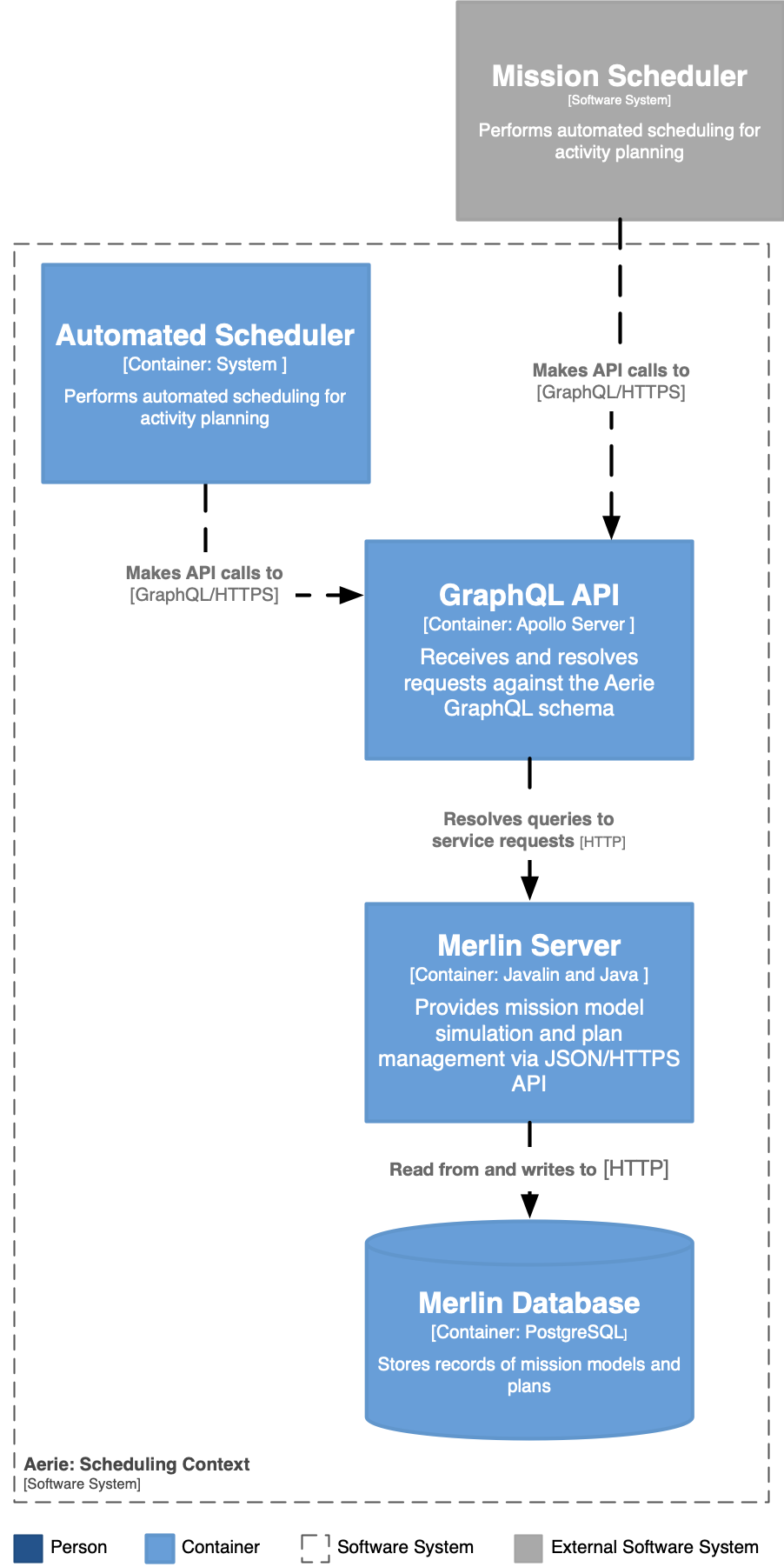
Scheduling
Just as a human operator places and edits activities in a mission plan, so too can an algorithmic agent can make automated decisions about activity plan editing. An automated scheduling agent enables missions to make a large volume of plan mutations and perform the complex evaluations as to how well such mutations achieve a mission's goals.
In Aerie the scheduling agent "Automated Scheduler" exists as a separate entity and makes queries and mutation against the Aerie API. As shown in the Figure below, an Aerie developed and maintained automated scheduler is a part of the standard Aerie deployment. The Aerie Automated Scheduler makes queries of simulation results, constraint evaluations, and makes plan mutations via the Aerie API. This loose coupling is the same as any third party entity which may query the Aerie API gateway. As a result, a mission can choose to forgo the Aerie Automated Scheduler and implement their own scheduler and scheduling algorithm, which makes use of the same Aerie API.
Previous activity planning and simulation systems chose to embed scheduling logic within the mission model code base. Such tight coupling of scheduling logic with the mission model code introduced particularly burdensome restrictions. The loose coupling of the Aerie design alleviates these burdens and is characterized by the following aspects:
- Expressivity - restrictions on expressivity (using other programming paradigms to develop scheduling algorithms and evaluate scheduling rules)
- Extensibility - extensibility (definition of new constraint concepts without having to modify any part of Aerie or a mission model)
- Maintainability - disconnect the mission model and scheduling editing CM process
- Process independence/async - run on different infrastructure providing performs, and more dynamic execution workflows
When executing the Automated Scheduler is likely to make many calls to the Aerie API. The Automated Scheduler will sensibly batch API calls to reduce unnecessary communication round trips. A scheduler will need to be able to make the following requests of the Aerie API:
- Query for activity instances in a plan
- Add, edit, delete activity instance from a plan
- Simulate an activity plan for some duration from some start time
- Query simulated resource profiles
- Add/edit/delete constraints for a plan
- Query constraint windows for a plan
- Submit a constraint definition for its windows for a plan
Appendix
A - The C4 Model
The architectural diagramming approach taken in this document follows the C4 Model for visualizing and discussing software architecture. This approach abstracts a software system into roughly four level, Context, Containers, Components, and Code. A brief overview of the first three levels of abstraction is given below to help the reader of this document better understand what is being communicated in the various diagrams.
The Context diagram shows the software system (Aerie) in its broadest scope.
Scope: A single software system.
Primary elements: The software system in scope.
Supporting elements: People (e.g., users, actors, roles, or personas) and software systems (external dependencies) that are directly connected to the software system in scope. Typically, these other software systems sit outside the scope or boundary of your own software system, and you don’t have responsibility or ownership of them.
Intended audience: Everybody, both technical and non-technical people, inside and outside of the software development team.The Container diagram shows the high-level shape of the software architecture and how responsibilities are distributed across it. It also shows the major technology choices and how the containers communicate with one another. A container is a separately runnable/deployable unit (e.g., a separate process space) that executes code or stores data.
Scope: A single software system.
Primary elements: Containers within the software system in scope.
Supporting elements: People and software systems directly connected to the containers.
Intended audience: Technical people inside and outside of the software development team; including software architects, developers and operations/support staff. Notes: This diagram says nothing about deployment scenarios, clustering, replication, failover, etc.The Component diagram specifies the "components" which comprise a Container, what each of those components are, their responsibilities and the technology/implementation details.
Scope: A single container.
Primary elements: Components within the container in scope.
Supporting elements: Containers (within the software system in scope) plus people and software systems directly connected to the components.
Intended audience: Software architects and developers.